
It is a rainy day, all work is done and I make myself comfortable on my sofa. A push of a button, the TV and the UPC TV Box switch on. I zap my way through the jungle of media entertainment. I ask myself the question, how do the TV channels actually get into the small UPC TV Box? As a consumer of TV entertainment, I switch channels and they’re just there. Is it technically that simple? We answer this question here.
Leimbach, for some an agglomeration area in Zurich, for UPC the home of the TV headend.
We are on site, it is around 9 am and our colleague Gilbert, Senior Manager of the T&I TV Operations department, will give us some impressive information about the network structure and the headend. We go to a meeting room and Gilbert introduces us to the theory.
The UPC supply area is distributed throughout Switzerland and is supplemented by various partner networks. The signal flow is ensured by different types. The reception of TV and radio programs for the UPC coverage area is ensured via terrestrial reception, satellite reception, optical fiber (FOC) or IP feeds. In addition, Internet signal sources are used for a few radio programs (streams). The source of the TV signal plays no role for us. From a technical point of view, everything can be received and processed with the appropriate equipment so that the receivers can play it back. Let’s go into the topic of the different reception sources:
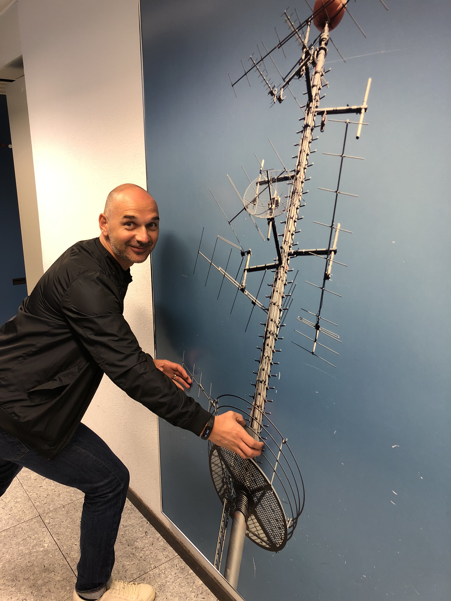
TV reception via terrestrial signal
The transmission masts of the terrestrial TV antennas have an approximate range of approx. 20 kilometers. We use these signals mainly for the radio offer. Among others, we have antenna sites in Basel and Geneva, which also receive TV signals from France, in Ticino towards Northern Italy for the Italian stations, in Lucerne and Zurich for radio stations, etc. The analogue radio signals are digitized by us after reception. If the radio/TV programs are received digitally, in DAB, DVB-T, etc., we include these on us and feed them digitally into our network. The law in Switzerland allows us to intercept free-to-air transmitters and then feed them into our cable network. We therefore use this method when the foreign transmitters transmit the signal at the border regions.
TV reception via satellite
Over 3000 TV and radio stations are broadcast via satellite. About 75% of them are encrypted. Our locations in Zurich Üetliberg, Otelfingen and Zurich Leimbach are equipped with large antennas which receive the TV channels and feed them into our headend. In order to be able to decode the channels, we need contracts with the broadcasting stations that allow us to distribute them. The received program is decrypted, processed and encoded by our own encryption.
TV reception via fiber optic cable
Via FO we receive various TV signals directly from the TV studios in digital form. As an example there are the stations TeleZüri, Tele Ostschweiz, TeleBärn, etc.. Since these channels are not broadcast via satellite, we use fiber optic cable technology to transmit the signal from their studio to us. In Swiss television we use both signals - via satellite and via FO. Here we have redundancy in the event of a signal failing. Also from Munich (Pro7/Sat1) and from Cologne (RTL Group) we get the signals via FO.
IP
We receive 2-3 radio programs via studio directly with the IP technology.
With all these technologies we have about 600 TV channels and 300 radio programs on offer.
We would like to prevent failures of stations. We achieve this with a redundancy through our backbone, as well as the feeding of channels via various technologies described above. Our TV backbone leaves the headend in Leimbach in two directions around Switzerland. Let’s call it the Blue Backbone and the Red Backbone. The blue one leaves the building in Leimbach from the left and the red one from the right. The backbone then crosses the whole of Switzerland in both directions back to Leimbach. There are about 50 sub-headends in the supply area, which pick up the digital TV/radio signal from the backbone. From there they are distributed at so-called HUB’s (150 units). These in turn assign the signal to our nodes (approx. 2500). From the node on, the signals are converted from optical to electrical. The electrical signals now reach the connected buildings from the nodes. From there directly via TV can to the receivers of the customers.
Transmission rates of the TV signals
The TV channels in SD, HD and UHD quality are widespread in our coverage area. The graphic below illustrates the transmission rates of the respective qualities.

From reception to distribution of the signal
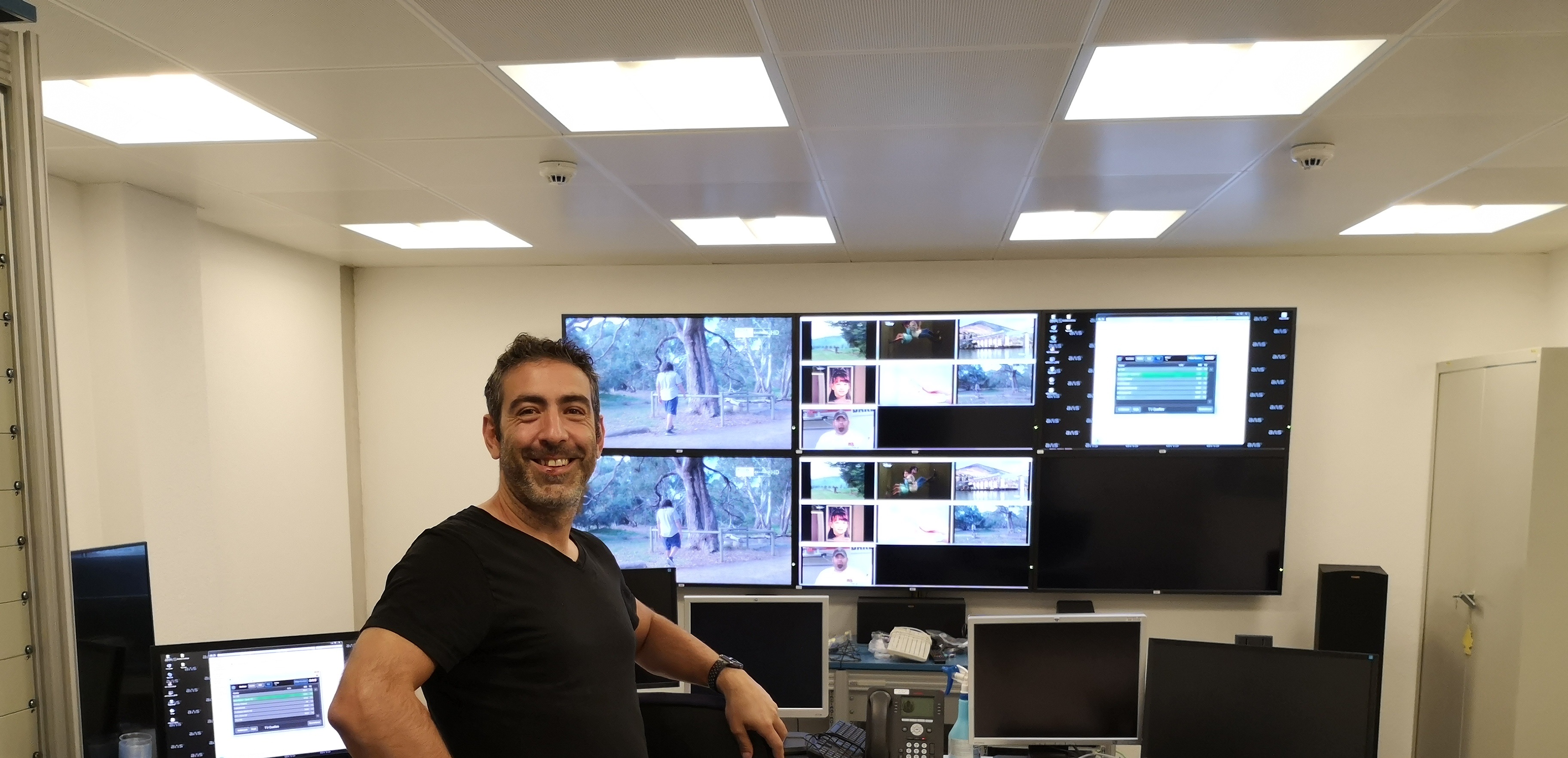
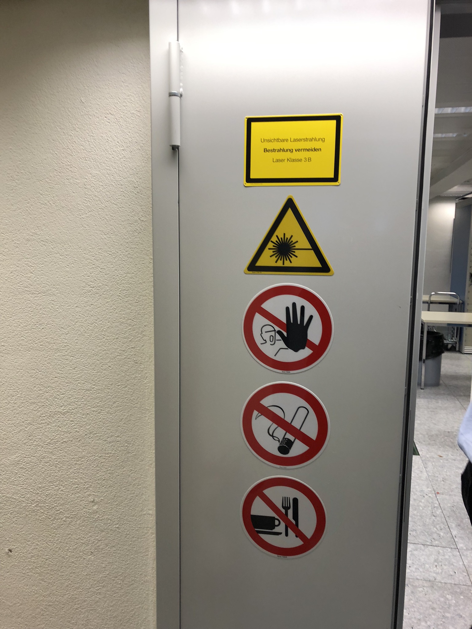
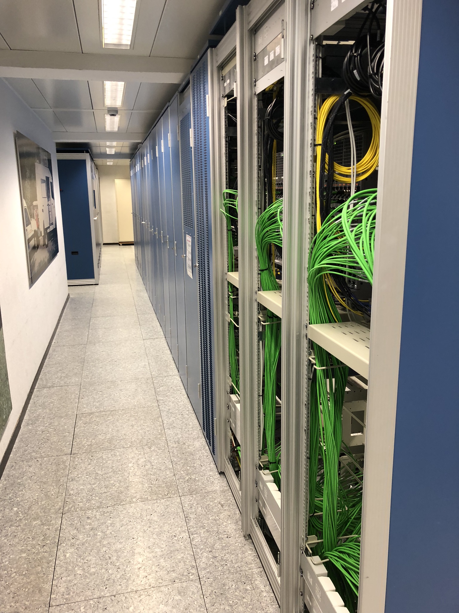
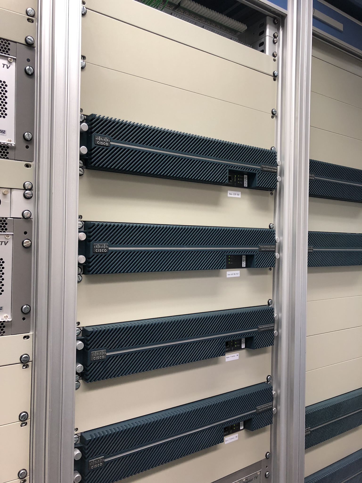
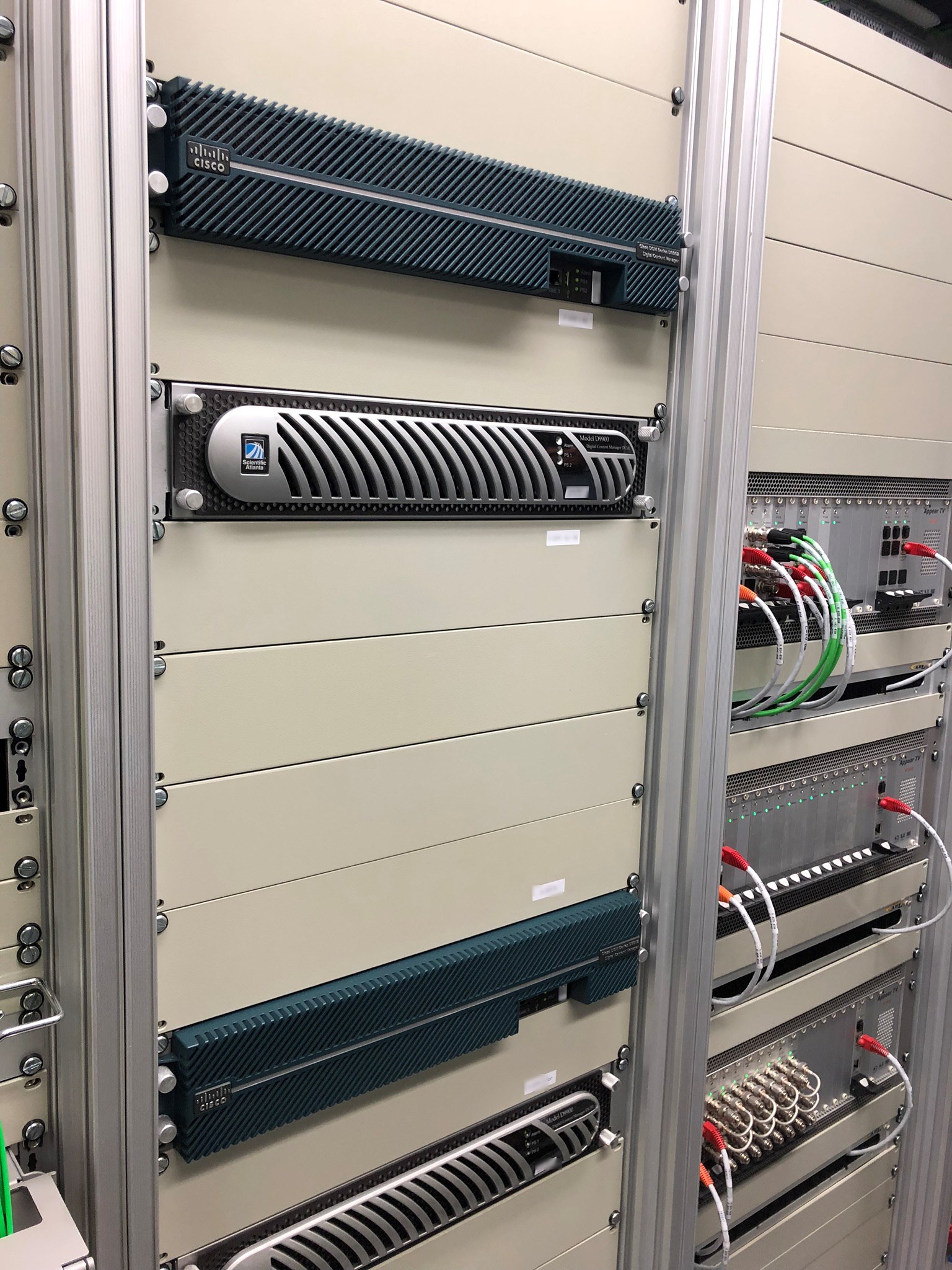
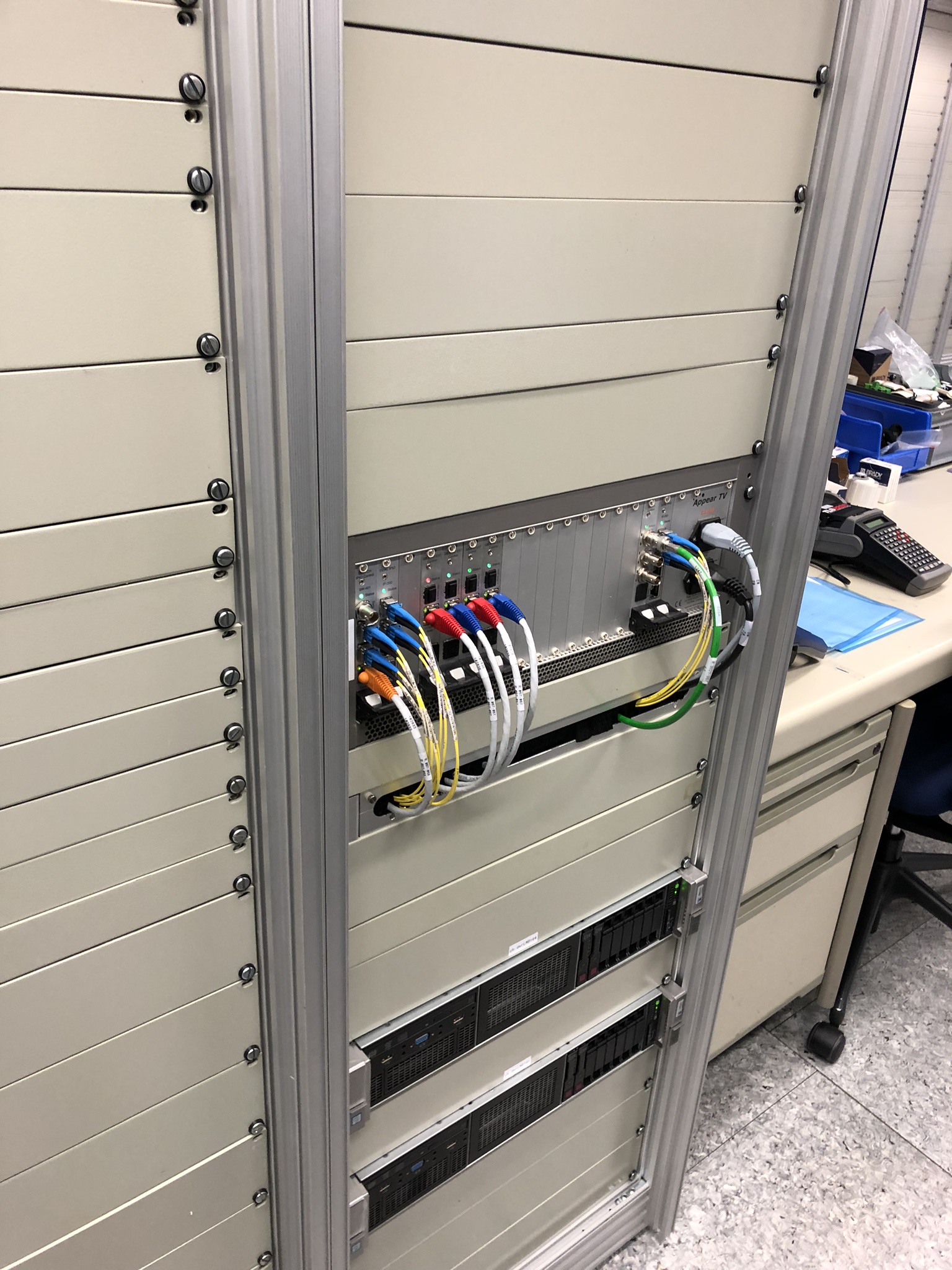
After a few hours of theory, we get an insight into the technical room. We go down the stairs to the lowest floor. The entrance door is equipped with warning signs. Gilbert opens the door and the buzz of cooling fans fills the room. We stop, marvel and can’t believe how many electronic devices, switches, transcoders, coders, receivers, etc. provide the room.
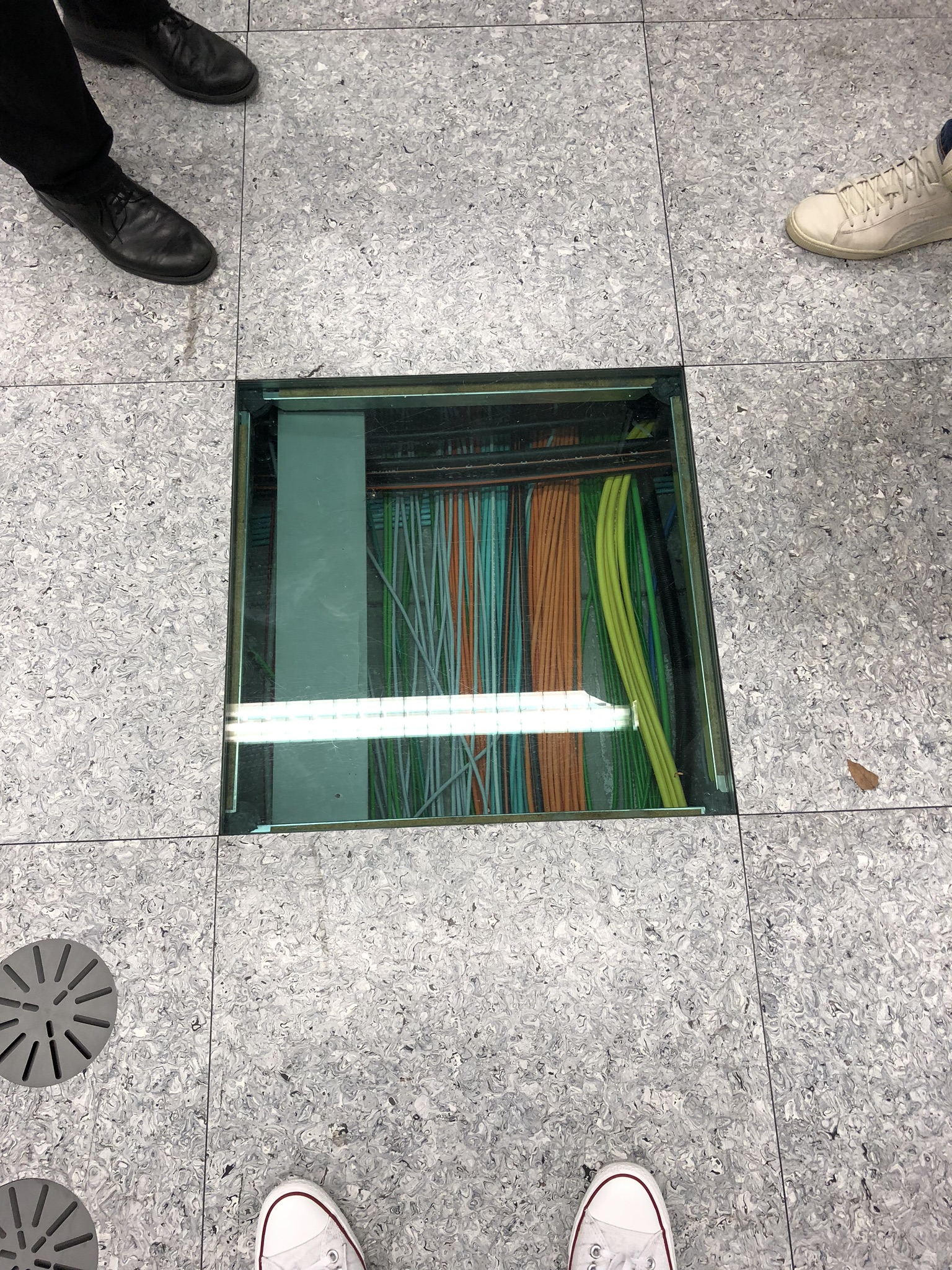
Step by step Gilbert guides us through the different connected devices and explains the operational purpose. On the pictures below we share with you the picture gallery of the headend tour. We have commented the photos at the end of this article, what exactly can be seen on them.
Focus on our environment
Gilbert ends the tour with a remark about electricity consumption. We used to cool down the equipment, or rather the room, to 21 degrees Celsius. So that we can reduce the electricity consumption and make our contribution to the environment, we have raised the temperature to 24 degrees. This is the case for all Headends, Sub-Headends and HUBs in Switzerland.
We say goodbye to our colleague Gilbert, thank him for the leadership and move on. Arriving home again in the evening, I switch on the UPC TV Box. I choose an exciting program and imagine now which way the TV signal crosses; satellite - headend - decryption - processing - encryption - backbone - subheadend - HUB- node - TV can - UPC TV box. Unbelievable, all this still in a speed, which is hardly imaginable.
Back to the initial question whether this is technically so easy I have to admit that this is not the case. In the background it has an enormous complexity. Very impressive for me as an entertainment lover. What do you think?
NOTES:
- Sub-Headend: Location where the radio/TV programs are “taken down” from the backbone so that they can be distributed in this region / network.
- Node: Cabin with devices that convert the optical signal into an electrical signal, including further amplifiers for the electrical signal.
- RTV backbone: optical connections, feeds through which the TV/radio signals are transported from the headend to the sub-headends ( feeder transport network).

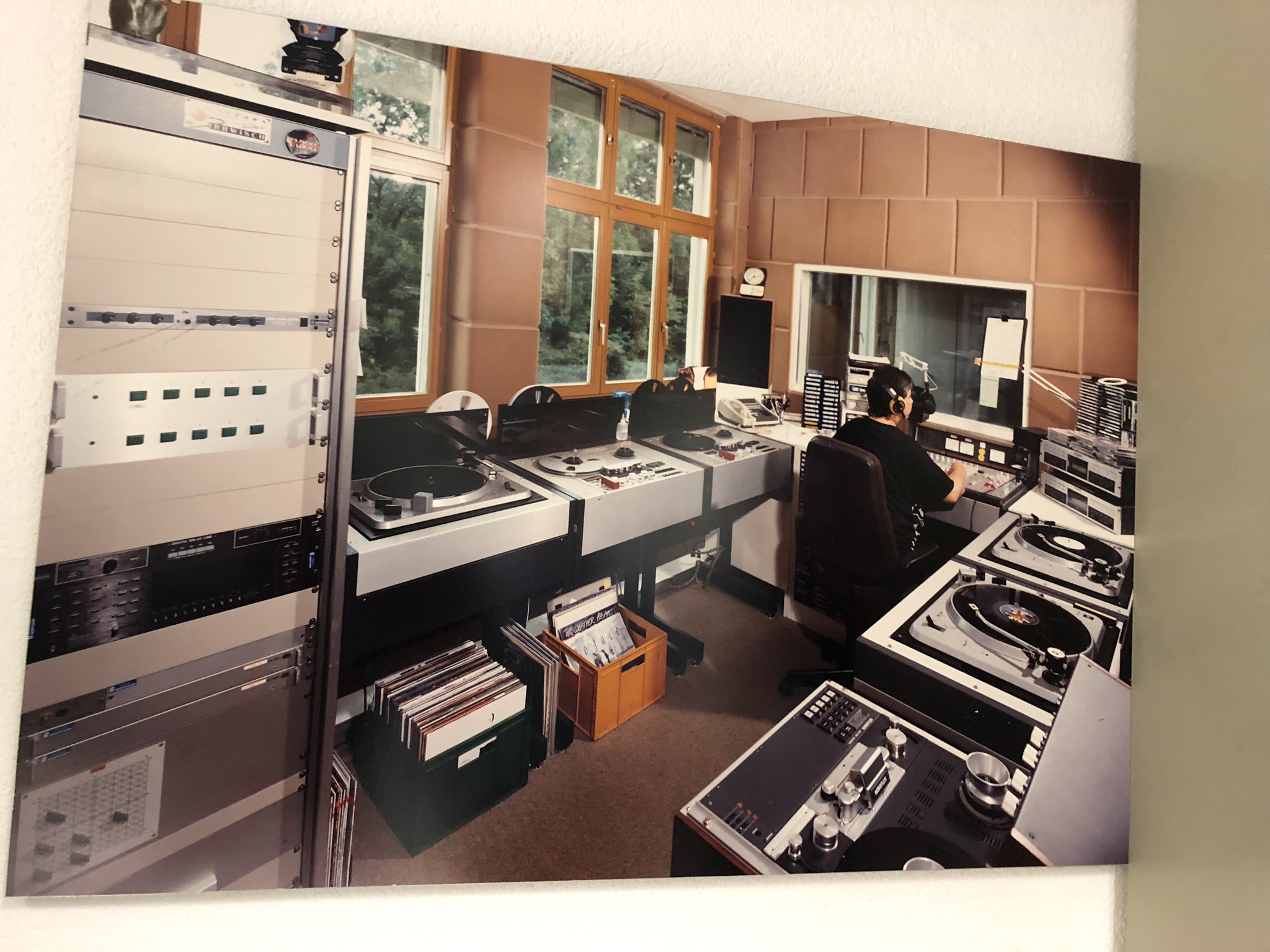 Radio Station from Rediffusion Times
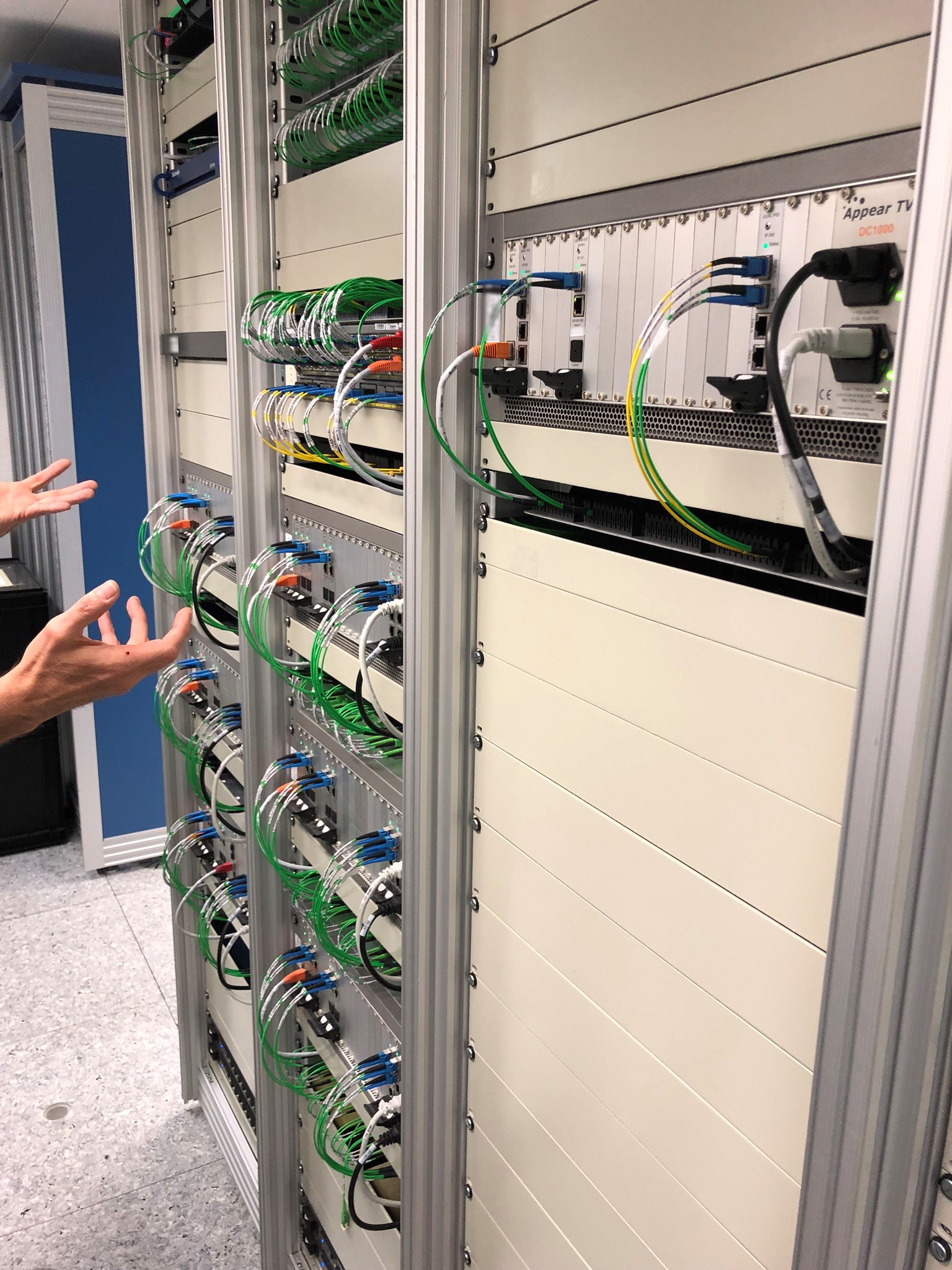 RTV backbone entry (distribution of signals via the blue & red ring)
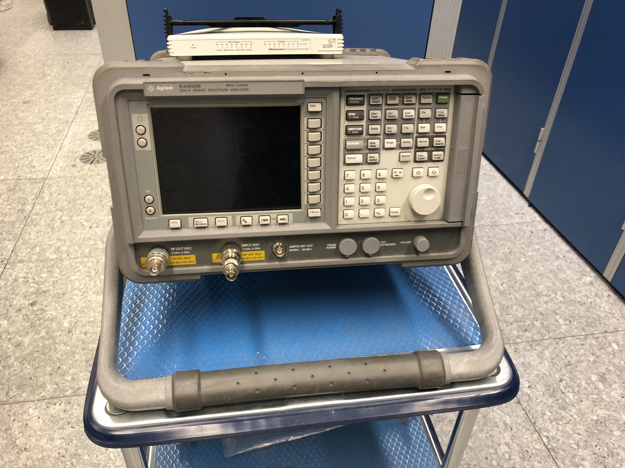 HF measuring device
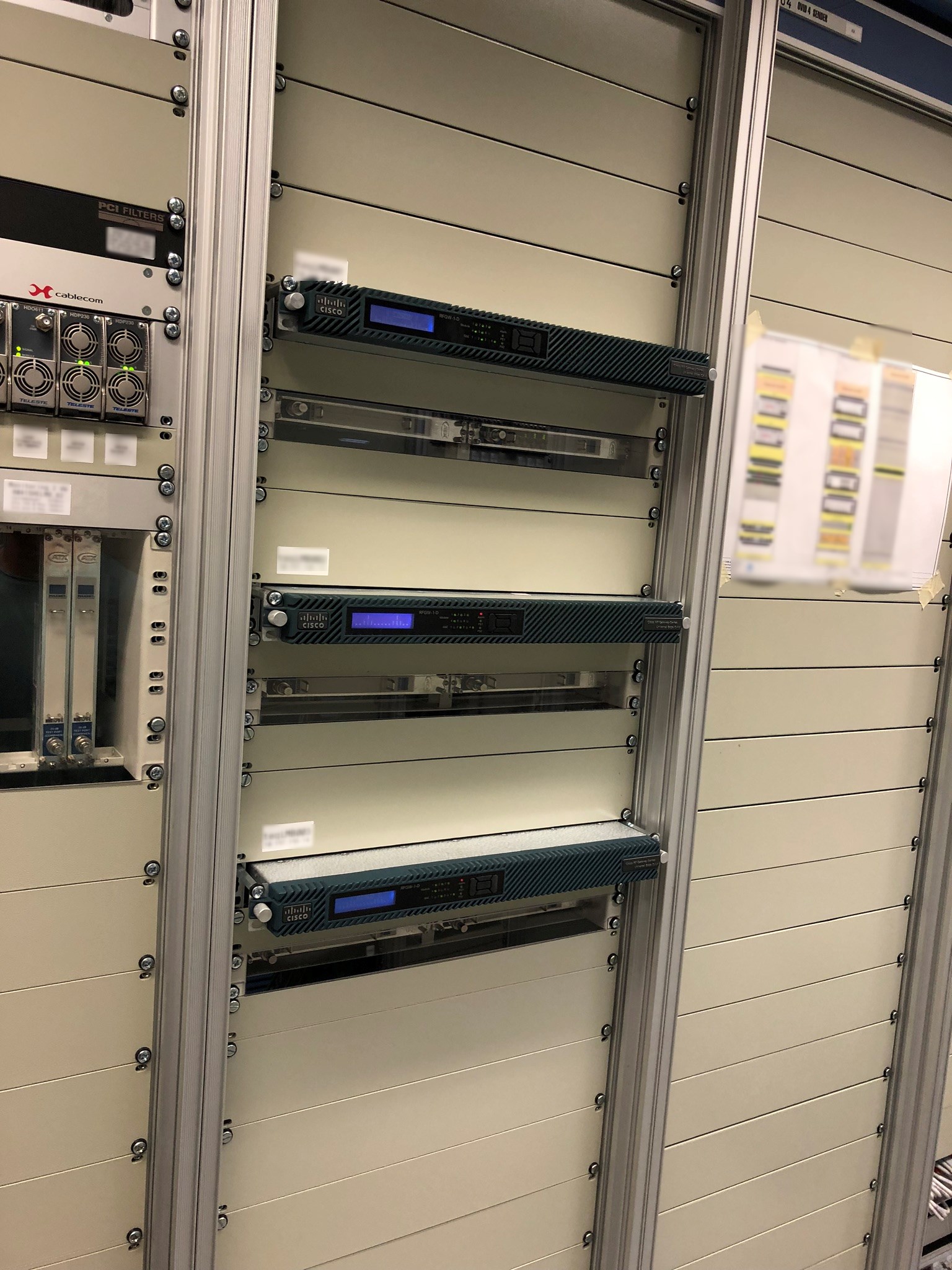 HF QAM modulators
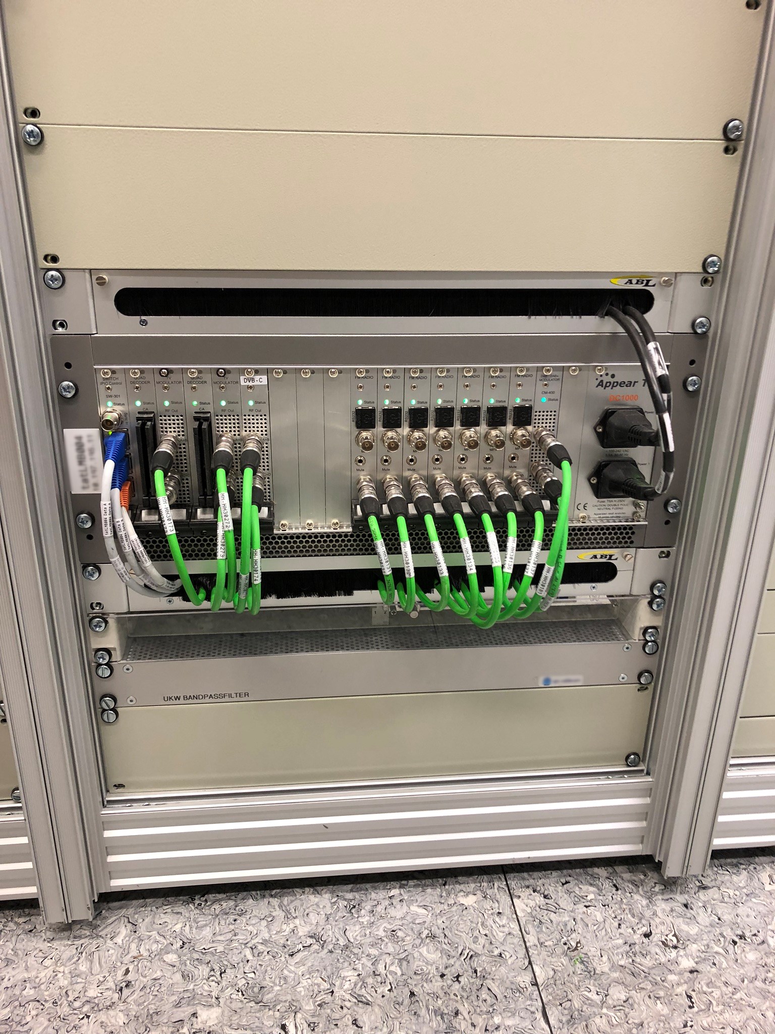 System for analogue FM/UKW radio programs
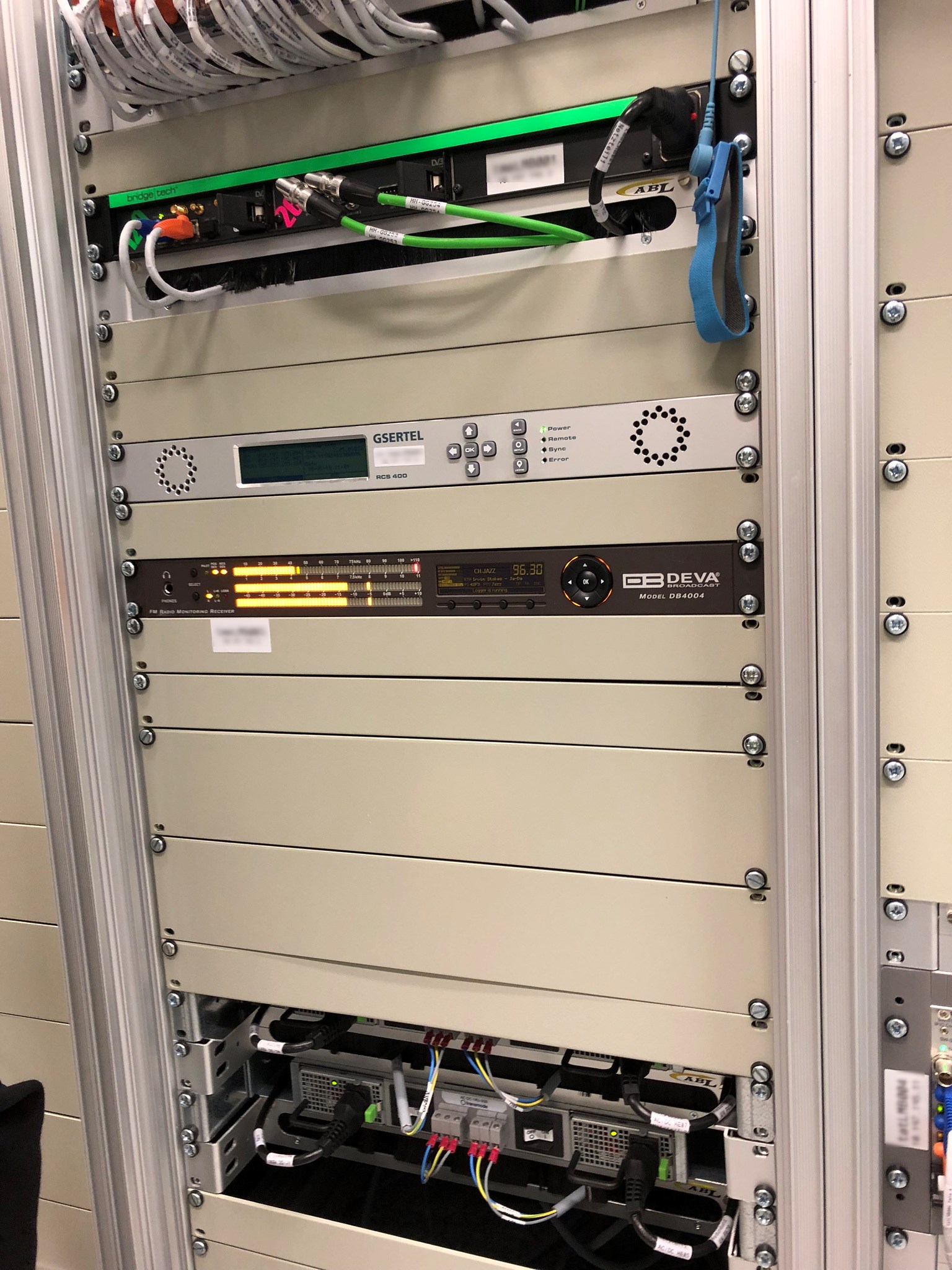 (devices in the middle): measuring instruments for quality assurance and fault location
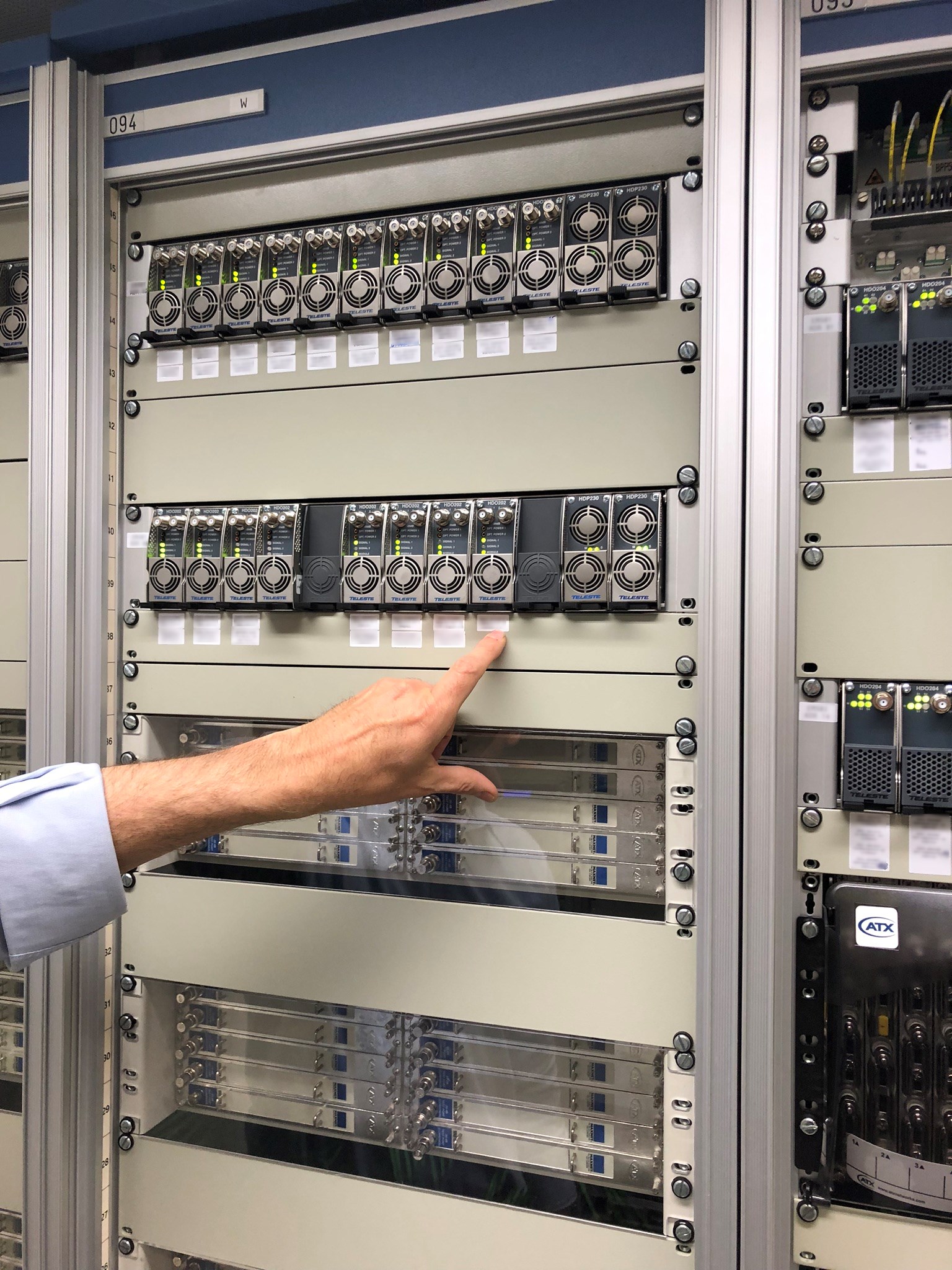 Return path interconnection: Optical receivers (HDO202) that convert the return path signal from the nodes from optical to electrical (coax). Then it goes from there to the CMTS.
 Backbone Map
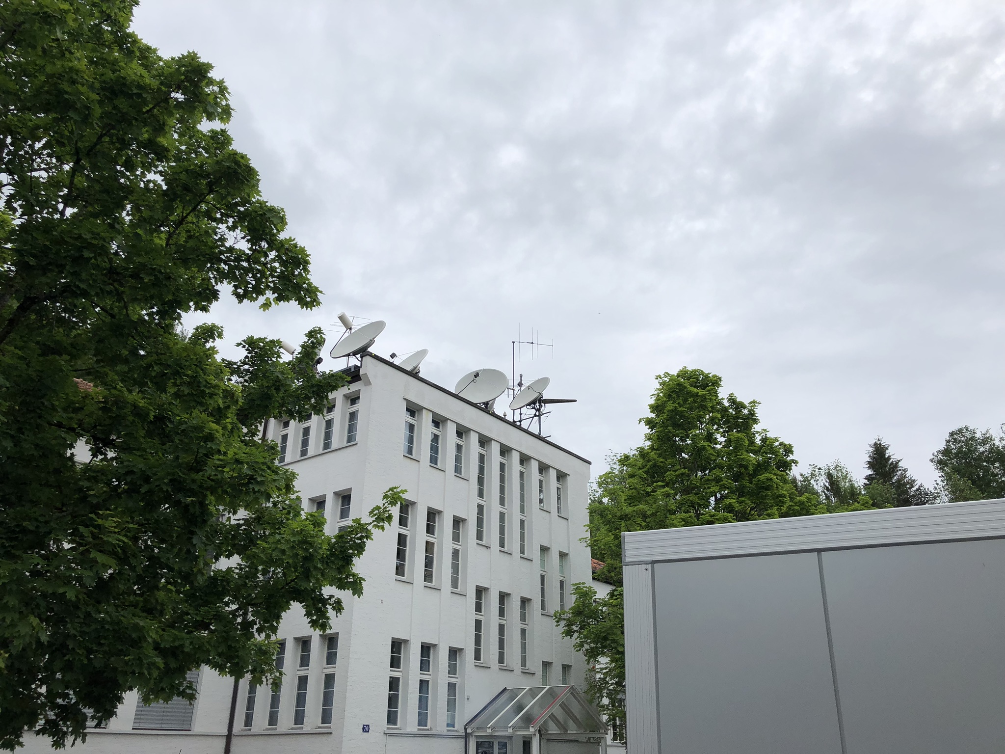
 Multiplexer for TV and radio programs
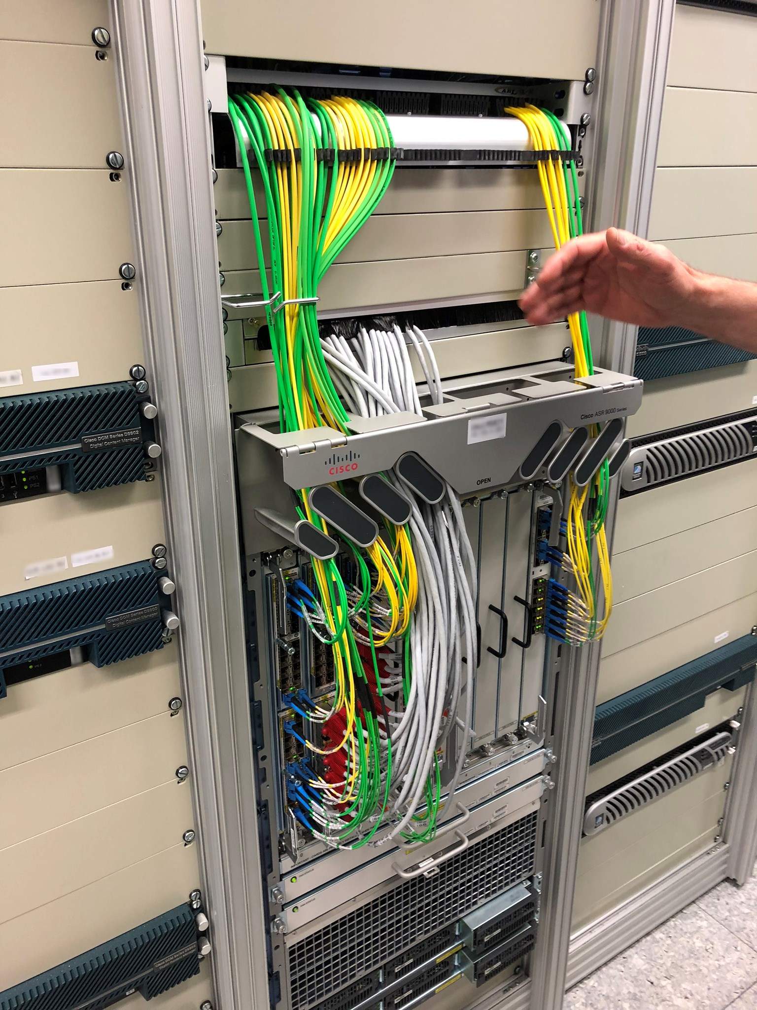
(Behind the Scenes - Day 2 - The UPC Headend)